1% accuracy pneumatic level controller fisher 2500
1% accuracy pneumatic level controller fisher 2500

fisher 2500

fisher 2500
UTZ-P 2500-249 Series Pneumatic Controllers and Transmitters
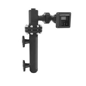
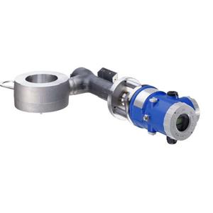
Typical caged and cageless sensor/instrument
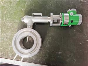
configurations are shown in figures 1 and 2. Caged sensors (figure 3) provide more stable operation
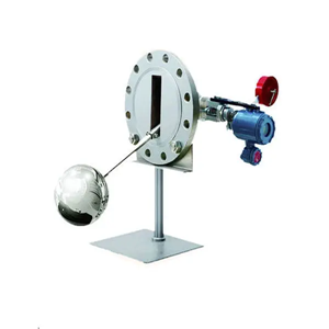
than do cageless sensors (figure 4) for vessels with internal obstructions or considerable internal
turbulence. Cageless sensors are generally used on specific gravity and interface control applications
requiring large displacers that are more easily
accommodated by flange connections up to NPS 8. The availability of many different displacer stem
![]() lengths permits lowering the displacer down to the
lengths permits lowering the displacer down to the

most advantageous depth in the vessel.
UTZ-P pneumatic controllers and transmitters are
used wherever rugged, dependable, and simply
constructed displacer-style pneumatic
instrumentation is required in liquid level, interface level, or density service. The ruggedness of these products is demonstrated by their use in many kinds of demanding applications, including those in the
power, chemical process, oil and gas production,
Product Bulletin
2500-249 Controllers and Transmitters Nove![]() be.r:2009
be.r:2009
Available Configurations Input Signal Fluid Level or Fluid-to-Fluid Interface Level: From 0 to 100 percent of displacer length—standard lengths for all sensors are ■ 356 mm (14 inches) or ■ 813 mm (32 inches); other lengths available depending on sensor construction Fluid Density: From 0 to 100 percent of displacement force change obtained with given displacer volume—standard volumes are ■ 980 cm3 (60 inches3) for 249C and 249CP sensors or ■ 1640 cm3 (100 inches3) for most other sensors; other volumes available depending upon sensor construction Allowable Specific Gravity Specific gravity with standard volume displacers and standard wall torque tubes: Fluid Level and Fluid-to-Fluid Interface: 2500 Series, except 2503 and 2503R—Specific gravity range, 0.20 to 1.10 2503 and 2503R—Specific gravity range, 0.25 to 1.10 Fluid Density: 2500 Series, except 2503 and 2503R—Minimum change in specific gravity, 0.20 2503 and 2503R—Minimum change in specific gravity, 0.25 Contact your Emerson Process Management sales office for information on non-standard applications Output Signal See table1 Output Action ■ Direct (increasing fluid or interface level or specific gravity increases output pressure) or ■ Reverse (increasing fluid or interface level or specific gravity decreases output pressure) Area Ratio of Relay Diaphragms 3:1 Supply Pressure(1) Normal Operation: See table4 | Maximum to Prevent Internal Part Rupture(2): 3 bar (45 psig) Steady-State Air Consumption See table 4 Proportional Band, Differential Gap, or Span See table 1 Set Point (Controllers Only) Continuously adjustable to position control point or differential gap of less than 100 percent anywhere within displacer length (fluid or interface level) or displacement force change (density) Zero Adjustment (Transmitters Only) Continuously adjustable to position span of less than 100 percent anywhere within displacer length (fluid or interface level) or displacement force change (density) Performance Independent Linearity (Transmitters Only): 1 percent of output pressure change at span of 100 percent Hysteresis: 0.6 percent of output pressure change at 100 percent of proportional band, differential gap, or span Repeatability: 0.2 percent of displacer length or displacement force change Deadband (Except Differential Gap Controllers(3)): 0.05 percent of proportional band or span Typical Frequency Response: 4 Hz and 90-degree phase shift at 100 percent of proportional band, differential gap, or span with output piped to typical instrument bellows using 6.1 meters (20 feet) of 6.4 mm (1/4-inch) tubing Ambient Temperature Error: ± 1.5 percent of output pressure change per 28。C (50。F) of temperature change at 100 percent of proportional band, differential gap, or span when using sensor with standard wall N05500 torque tube Reset (Proportional-Plus-Reset Controllers Only): Continuously adjustable from 0.005 to over 0.9 minutes per repeat (from 200 to under 1.1 repeats per minute) Anti-Reset Differential Relief (2502F and 2502FR Controllers Only): Continuously adjustable from 0.14 to 0.48 bar (2 to 7 psi) differential to relieve excessive difference between proportional and reset pressures |
-continued-
Product
34.2:2500 November
Bulletin
2009
![]() 2500-249 Controllers and Transmitters
2500-249 Controllers and Transmitters
Standard Tubing Connections 1/4 NPT internal Sensor Connection Sizes Maximum Working Pressures (Sensors Only)(1) Consistent with applicable ASME pressure/temperature ratings for the specific sensor constructions shown in tables 5 and 6 Operative Ambient Temperatures(1) Controller ■ Standard -40 to 71。C (-40 to 160。F) ■ High Temperature -18 to 104。C (0 to 220。F) Sensor See table 2 For ambient temperature ranges, guidelines, and use of optional heat insulator, see figure 5 Standard Supply and Output Pressure Gauge Indications See table 4 | Allowable Process Temperatures(1) See table 2
Hazardous Area Classification 2500 Series controllers comply with the requirements of ATEX Group II Category 2 Gas and Dust
Construction Materials Mounting Positions See figure 10 Caged Sensor Connection Styles See figure 11 Options See Options section |
NOTE: Specialized instrument terms are defined in ANSI/ISA Standard 51.1 - Process Instrument Terminology.
1. The pressure/temperature limits in this document and any applicable code or standard should not be exceeded.
2. Also see Supply Pressure Overpressure Protection section.
3. For 2500S, 2500SC, and 2503 adjusting the differential gap is equivalent to adjusting the deadband.
Features
● Easy Adjustment—Set point, proportional valve opening, and reset changes are made with simple dial-knob controls.
● Simple, Durable Construction—Few moving parts are used. Knife-edged driver bearing in sensor and plated brass instrument case ball bearing for
torque tube rotary shaft help provide low-friction operation. Sensors are available in ratings up to CL2500.
● Mounting Versatility—Caged sensors are
available in a variety of orientations and connection styles, and all sensors can be either right- or
left-hand mounted.
● Sensitive to Small Changes—Displacer
reaction to small specific gravity changes allows
these instruments to be used for density applications
and in other applications where a response to low levels of input signal change is required.
● Easy Reversibility—Action is field reversible from direct to reverse or vice versa without additional parts.
● Reduced Maintenance Costs—Spring-out wire provides for in-service cleaning of relay orifice (figure 2). Torque tube can be replaced without
removing torque tube arm.
● Reduced Operating Costs—Supply pressure conservation is enhanced in all constructions
because relay exhaust opens only when output pressure is being reduced.
● Smaller Vessel Sizes Required for Stable
Control—Caged 249 Series sensors come standard with a liquid damping orifice in the lower equalizing connection that helps stability where vessel
capacitance is small and permits narrower proportional valve settings.
Product Bulletin
2500-249 Controllers and Transmitters Nove![]() be.r:2009
be.r:2009
Table 1. Additional Specifications for Selected UTZ-P 2500 Series Configurations
CONTROL OR TRANSMISSION MODE | TYPE NUMBER(1) | FULL OUTPUT SIGNAL CHANGE OBTAINABLE OVER INPUT OF: | OUTPUT SIGNAL | |
Proportional control | 2500, 2500C(2) | Proportional band of 0 to 100 percent of displacer length or displacement force change (10 to 100 percent recommended) | 0.2 to 1.0 bar (3 to 15 psig) or 0.4 to 2.0 bar (6 to 30 psig) | |
Proportional-plus-reset control | 2502, 2502C(2) | Proportional band of 0 to 200 percent of displacer length or displacement force change (20 to 200 percent recommended) | ||
Proportional-plus-reset control with anti-reset windup | 2502F | |||
Differential Gap (On-off) Control | With proportional valve and full differential gap adjustment | 2500S, 2500SC(2) | 0 and 1.4 bar (0 and 20 psig) or 0 and 2.4 bar (0 and 35 psig) | |
Without proportional valve- has limited differential gap adjustment |
2503 | Differential gap of approximately 25 to 40 percent of displacer length, when a 356 millimeter (14-inch) ideal-volume displacer is used on 1.0 specific gravity liquid level service and a standard 1.4 bar (20 psig) supply regulator setting is varied between 1.0 and 1.7 bar (15 and 25 psig)(3) |
0 and full supply pressure(4) | |
Proportional transmission | 2500T, 2500TC(2) | Span of 0 to 100 percent of displacer length or displacement force change (20 to 100 percent recommended) | 0.2 and 1.0 bar (3 to 15 psig) or 0.4 to 2.0 bar (6 to 30 psig) | |
1. The suffix R is added to the type number for reverse action, and all types have a 67CFR supply regulator mounted as standard. 2. The suffix C is added to the type number for indicator assembly. 3. Other displacer lengths and volumes, or service conditions, will result in other differential gaps. 4. 1.4 bar (20 psig) and 2.4 bar (35 psig) are the standard factory-set supply regulator pressures, but these values will vary whenever the supply pressure is changed to adjust the differential gap. | ||||