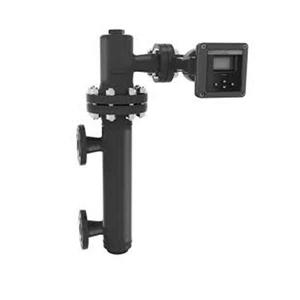
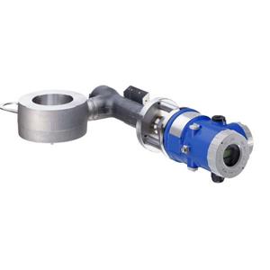
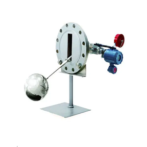
FISHER DLC3020F digital level controller
FISHER DLC3020F digital level controller
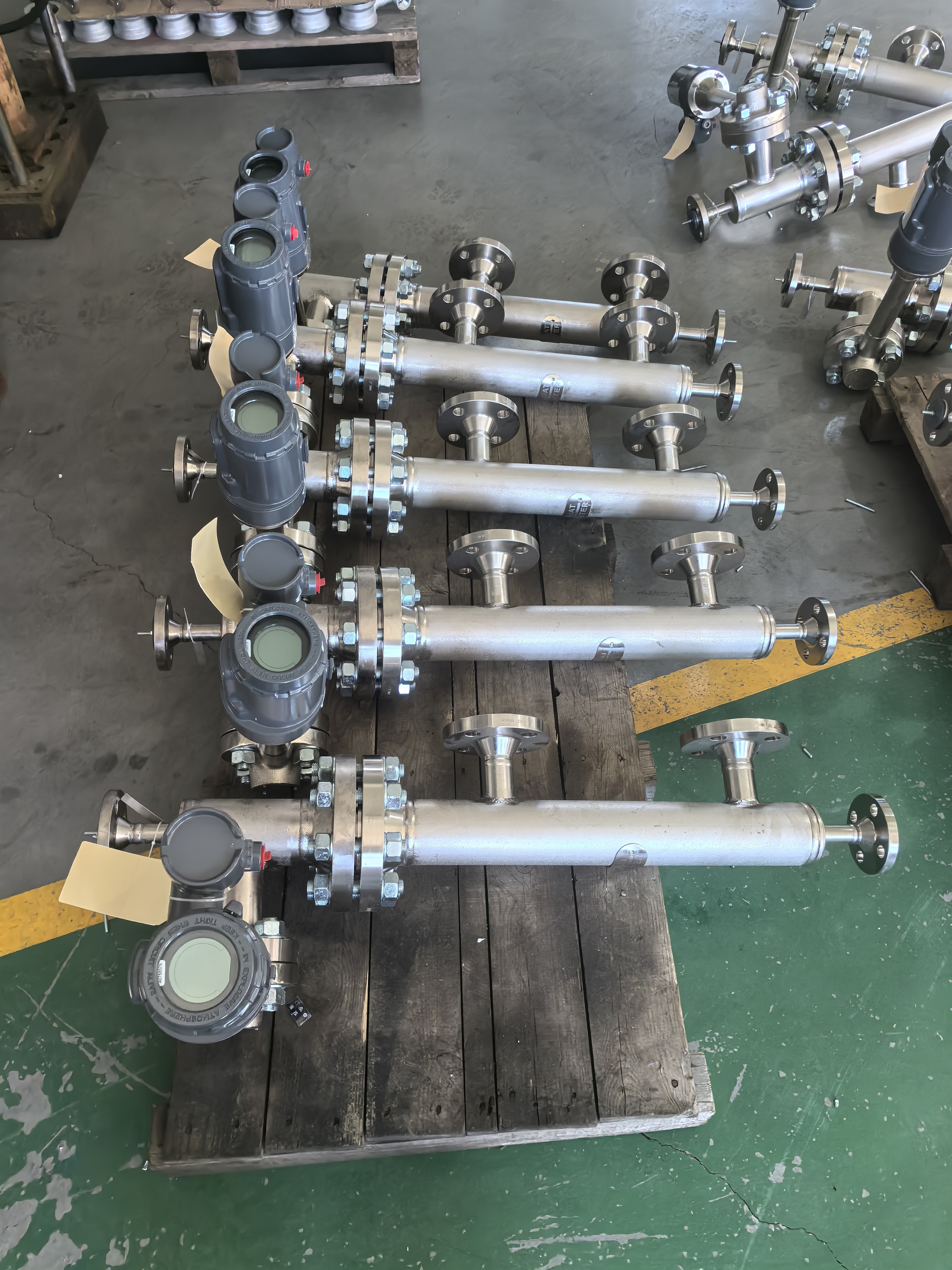
FISHER DLC3020F
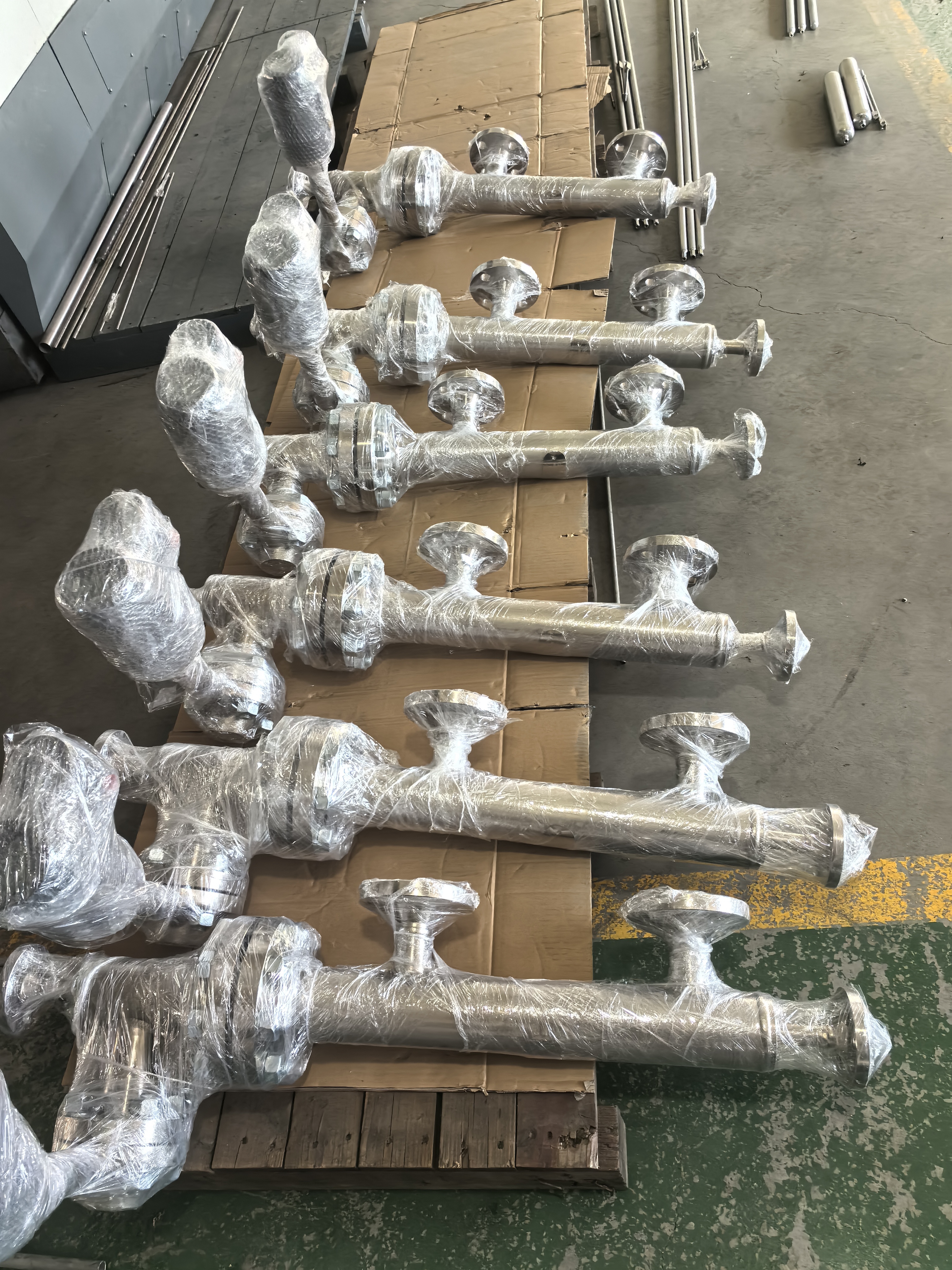
FISHER DLC3020F
Available Configurations Mounts on caged and cageless 249 sensors Function: Transmitter Communications Protocol: HART Input Signal Level, Interface, or Density(1): Rotary motion of torque tube shaft proportional to changes in liquid level, interface level, or density that change the buoyancy of a displacer. Process Temperature: Interface for 2- or 3-wire 100 ohm platinum RTD for sensing process temperature, or optional user-entered target temperature to permit compensating for changes in specific density. Output Signal Analog: 4 to 20 mA DC ■ Direct action—increasing level, interface, or density increases output; or ■ Reverse action—increasing level, interface, or density decreases output High saturation: 20.5 mA Low saturation: 3.8 mA High alarm(2): > 21.0 mA Low Alarm(2): < 3.6 mA Digital: HART 1200 Baud Frequency Shift Keyed (FSK) HART impedance requirements must be met to enable communication. Total shunt impedance across the master device connections (excluding the master and transmitter impedance) must be between 230 and 600 ohms. Supply Requirements (see figure 3) 12 to 30 volts DC; 25 mA Instrument has reverse polarity protection. A minimum compliance voltage of 17.75 VDC (due to HART impedance requirement) is required to guarantee HART communication. Transient Voltage Protection
| Electrical Classification Overvoltage Category II per IEC 61010 clause 5.4.2 d Pollution Degree 4 Altitude Rating Up to 2000 meters (6562 feet) Ambient Temperature The combined temperature effect on zero and span without the 249 sensor is less than 0.02% of full scale per degree Celsius over the operating range -40 to 80oC (-40 to 176oF) LCD operating temperature limits -20 to 70oC (-4 to 158oF)(3) Process Temperature The process density and torque rate are affected by the process temperature (see figure 5). Temperature compensation can be implemented to correct for process density changes. Process Density The sensitivity to error in knowledge of process density is proportional to the differential density of the calibration. If the differential specific gravity is 0.2, and error of 0.02 specific gravity units in knowledge of a process fluid density represents 10% of span. Hazardous Area Approvals CSA Class/Division: Intrinsically Safe, Explosion-proof(4), Division 2, Dust Ignition-proof Zone: Intrinsically Safe, Flameproof, Type n, Dust by intrinsic safety and Enclosure ATEX/IECEx—Flameproof, Intrinsic Safety, Dust by Intrinsic Safety Electrical Housing IP66, Type 4X
Electrical Connections Two 1/2-14 NPT internal conduit connections. Both are at the bottom of terminal box. | ||||||||||
-continued-

Electromagnetic Compatibility DLC3100 meets EN61326-1:2013 Performance is shown in table 1 DLC3100 SIS meets EN61326-3-2:2008 Performance is shown in table 2 DLC3100 SIS Safety Instrumented System Classification SIL2 capable - certified by exida Consulting LLC Performance
NOTE: At full design span, reference conditions. 1. To lever assembly rotation inputs. At effective proportional band (PB)<100%, linearity, dead band, and repeatability are derated by the factor (100%/PB) | Minimum Differential Specific Gravity 0.05 SGU
Construction Materials Housing and Cover: Low-copper aluminum die casting alloy Internal: Aluminum, and stainless steel; encapsulated printed circuit board Lever assembly: Plated steel, neodymium iron boron magnets Hall Guard: Thermoplastic elastomer
Weight Less than 3.45 kg (7.57 lb)
Options ■ Heat insulator(5) (see figure 2 for use guidelines) ■ Mountings for Masoneilan, Yamatake and Foxboro-Eckhardt sensors |
1. Density application is not available in DLC3100 SIS.
2. Only one of the High/Low alarm definition is available in a given configuration. Both alarms are NAMUR NE43 compliance.
3. Outside of this limit, LCD will not be readable but it will not affect the functionality of DLC3100 if the temperature is still within the operating limits. Push buttons will be disabled when instrument temperature is below -20°C (-4°F) or above 70°C (158°F) where LCD display might be intermittent.
4. Not for use in Ester and Ketone atmospheres.
5. If the DLC3100 and a 249 sensor are ordered as an assembly, and a heat insulator is required for the application, order the heat insulator as a 249 sensor option.
If the DLC3100 is ordered separately, the heat insulator is available as a kit.
Table 1. DLC3100 EMC Results— EN61326-1
Port | Phenomenon | Basic Standard | Test Level | |
Enclosure | Electrostatic discharge (ESD) | IEC 61000-4-2 | 4 kV contact 8 kV air | A |
Radiated EM field | IEC 61000-4-3 | 80 to 1000 MHz @ 10V/m with 1 kHz AM at 80% 1400 to 2000 MHz @ 3V/m with 1 kHz AM at 80% 2000 to 2700 MHz @ 1V/m with 1 kHz AM at 80% | A | |
Radiated power frequency magnetic field | IEC 61000-4-8 | 30 A/m at 50 and 60 Hz | A | |
I/O signal/control | Burst | IEC 61000-4-4 | 1 kV | A |
Surge | IEC 61000-4-5 | 1kV (line to ground only, each) | B | |
Conducted RF | IEC 61000-4-6 | 150 kHz to 80 MHz at 3 Vrms | A | |
Protective earth | Burst | IEC 61000-4-4 | 2 kV | A |
Surge | IEC 61000-4-5 | 2 kV (line to ground only) | B | |
Conducted RF | IEC 61000-4-6 | 150 kHz to 80 MHz at 3 Vrms | A | |
1. A = No degradation during testing. B = Temporary degradation during testing, but is self_recovering. Specification limit = +/- 1% of span. 2. HART communication was considered as “not relevant to the process” and is used primarily for configuration, calibration, and diagnostic purposes. | ||||
Table 2. DLC3100 SIS EMC Summary Results—Immunity per EN61326-3-2
Phenomenon | Basic Standard | Test Level | ||
Enclosure | Electrostatic discharge (ESD) | IEC 61000-4-2 | 6 kV contact 8 kV air | A |
Radiated EM field | IEC 61000-4-3 | 80 to 1000 MHz @ 10V/m with 1 kHz AM at 80% 1400 to 2000 MHz @ 10V/m with 1 kHz AM at 80% 2000 to 2700 MHz @ 3V/m with 1 kHz AM at 80% | A | |
Radiated power frequency magnetic field | IEC 61000-4-8 | 100 A/m at 50 and 60 Hz | A | |
I/O signal/control | Burst | IEC 61000-4-4 | 1 kV | A |
Surge | IEC 61000-4-5 | 1 kV (line to ground only, each) | FS | |
Conducted RF | IEC 61000-4-6 | 10 kHz to 80 MHz at 10 Vrms | A | |
Protective earth | Burst | IEC 61000-4-4 | 2 kV | A |
Surge | IEC 61000-4-5 | 1 kV (line to ground only) | A | |
Conducted RF | IEC 61000-4-6 | 10 kHz to 80 MHz at 10 Vrms | A | |
1. A = No degradation during testing. B = Temporary degradation during testing, but is self_recovering. FS = Fail Safe. Specification limit = +/- 2% of span. 2. HART communication was considered as “not relevant to the process” and is used primarily for configuration, calibration, and diagnostic purposes. | ||||