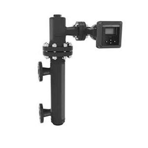
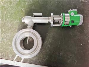
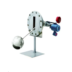
orifice flow meter from premier
orifice flow meter from premier
LG Series Orifice Flow Measurement Throttle Device
Summary
Throttle device is the most historic and most extensively used flow measurement instrument. Its features are simple structure, easy installation, stable performance and high accuracy, etc merits. It can be used for flow measurement for liquid, steam and gas in modern industries. There are many kinds of throttle devices with a whole variety (being conformability with Standard GB/T2624-2006, Standard ISO5167- 1-20031, Standard BS1042- 1989 and Standard ASME) that are manufactured with advanced calculation methods and precise manufacturing means. They are applied extensively in petroleum, chemical, power, light industry, water supply field, gas transmission field etc.
Principle of operation
A throttle element (like throttle orifice, throttle nozzle, etc) is installed in a pipe that is full of one way flowing continuous fluid. When the fluid passes the throttling orifice of the throttling element, the fluid stream forms local shrink. Then the velocity increases, so does the kinetic energy, the static pressure decreases. So, there is a differential static pressure from the fore and the rear of the throttle element, i.e. △P=P1-P2. If the area of the throttle orifice is F, the mass flow of the fluid is qm, the volume flow
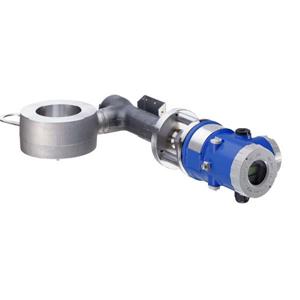
Orifice Throttling Device
Wenturi Tube Throttling Device
is qv the density is ρ, then according to the flow continuity law and Bernoulli equation, the following mathematical relations between differential pressure and fluid flow can be derived:
qm = αF · Δpp or qv =
“α” is flow coefficient. According to the above equation, if the area of the throttle orifice and fluid density are constant, flow has direct ratio with square root of differential pressure. That is to say, if you have the differential pressure value, then you can calculate the flow value. Throttle device can measuring fluid flow just according to this principle.
LG Series Orifice Flow Measurement Throttle Device
Model composition and meaning
LG □ □ --- □ □ □
Series number
Table 1 Throttling element code and meaning
Code | Meaning | Code | Meaning |
Y | Standard orifice plate | I | Eccentric orifice plate |
Q | 1/4 circle orifice plate | S | Segmental orifice plate |
X | Small caliber orifice plate | Z | Raw cast contracted section (throat) Classic Venturi Tube |
T | Taper inlet orifice plate | J | Machined contracted section (throat) Classic Venturi Tube |
M | ISA1932 ejection nozzle | H | Iron plate welded contracted section (throat) Classic Venturi Tube |
C | Major diameter ejection nozzle | W | Venturi ejection nozzle |
Table 2 Pressure measuring code and meaning
Code | F | H | Z | D | T |
Meaning | Pressure measuring with flange | Pressure measuring with angle joint ring chamber | Pressure measuring with drilling hole | Pressure measuring with two distanced holes | Special pressure measuring |
Table 3 Nominal diameter code and meaning
Code | 01 | 016 | 02 | 026 | 03 | 04 | 05 | 06 | 08 | 10 | ||||||||
DN | mm | 10 | 15 | 20 | 25 | 32 | 40 | 50 | 65 | 80 | 100 | |||||||
in |
| 1/2 | 3/4 | 1 | 1- 1/4 | 1- 1/2 | 2 | 2- 1/2 | 3 | 4 | ||||||||
| ||||||||||||||||||
Code | 12 | 15 | 20 | 25 | 30 | 35 | 40 | 45 | 50 | 60 | ||||||||
DN | mm | 125 | 150 | 200 | 250 | 300 | 350 | 400 | 450 | 500 | 600 | |||||||
in | 5 | 6 | 8 | 10 | 12 | 14 | 16 | 18 | 20 | 24 | ||||||||
Code | 70 | 80 | 90 | 91 |
|
|
|
|
|
| ||||||||
DN | mm | 700 | 800 | 900 | 1000 |
|
|
|
|
|
| |||||||
| in | 28 | 32 | 36 | 40 |
|
|
|
|
|
|
Table 4 Nominal pressure code and meaning
Code | 01 | 02 | 03 | 04 | 05 | 06 | 10 | 11 | 15 | 16 | |
PN | MPa | 1.6 | 2.0 | 2.5 | 4.0 | 5.0 | 6.3 | 10.0 | 11.0 | 15.0 | 16.0 |
Class |
| 150 |
|
| 300 |
|
| 600 | 900 |
| |
Code | 25 | 26 | 42 |
|
|
|
|
|
|
| |
PN | MPa | 25.0 | 26.0 | 42.0 |
|
|
|
|
|
|
|
Class |
| 1500 | 2500 |
|
|
|
|
|
|
| |
Table 5 Straight pipe section code and meaning
Code | No | A | B | C | D | E | F |
Meaning |
Throttle element |
Throttle element, with flange |
Throttle element, with flange, with upper and lower straight pipe section | Throttle element, with flange, with upper and lower straight pipe section, with upper and lower connection flange | Throttle element, with flange, with upper and lower straight pipe section, with upper connection flange | Throttle element, with flange, with upper and lower straight pipe section, with lower connection flange |
Welding structure |
2. Standards
2. 1. Standards for throttle element
Table 6 Standards for throttling element
Code | Meaning | Standards code |
Y | Standard orifice plate | GB/T2624-2006 (ISO5167-2003) |
Q | 1/4 circle orifice plate | BS1042- 1989 |
X | Small caliber orifice plate | GB2624-2006 |
T | Taper inlet orifice plate | BS1042- 1989 |
M | ISA1932 nozzle | GB/T2624-2006 (ISO5167-2003) |
C | Major diameter nozzle | GB/T2624-2006 (ISO5167-2003) |
I | Eccentric orifice plate | ASME |
S | Segmental orifice plate | ASME |
Z | Raw cast contracted section (throat) Classic venturi Tube | GB/T2624-2006 (ISO5167-2003) |
J | Machined contracted section (throat) Classic venturi Tube | GB/T2624-2006 (ISO5167-2003) |
H | Iron plate welded contracted section (throat) Classic venturi Tube | GB/T2624-2006 (ISO5167-2003) |
W | venturi nozzle | GB/T2624-2006 (ISO5167-2003) |
2.2 Flange & Gasket standards
Standards for flanges and gaskets: you can select JB Standard, HG20592 ~ 20614-2009 (European system), HG20615-20635-2009 (American system) or other standards1. Application range for
throttling elements
LG Series Orifice Flow Measurement Throttle Device
Installation dimensions of throttle device
1. 1.0-6.3 MPa installation dimensions of throttle device with flange pressure measuring
1. Flowing direction 2. Holeφ23 to be connected to the pressure measuring tube φ22
LG Series Orifice Flow Measurement Throttle Device
1.0MPa | Nominal diameter DN | D | LA | LB | LC |
10 | 90 | 126 | 276 | 422 | |
15 | 95 | 126 | 351 | 497 | |
20 | 105 | 128 | 428 | 586 | |
25 | 115 | 132 | 507 | 673 | |
32 | 135 | 132 | 612 | 786 | |
| |||||
40 | 145 | 138 | 738 | 924 | |
50 | 160 | 139 | 889 | 1075 | |
65 | 180 | 141 | 1116 | 1314 | |
80 | 195 | 146 | 1346 | 1552 | |
100 | 215 | 146 | 1646 | 1860 | |
| |||||
125 | 245 | 159 | 2034 | 2280 | |
150 | 280 | 159 | 2409 | 2655 | |
200 | 335 | 163 | 3163 | 3417 | |
For the above table, the length of the front straight section should be 10 times as long as the nominal diameter, the length of the rear straight section should be 5 times as long as the nominal diameter; For the below table, the length of the front straight section should be 2000mm, the length of the rear straight section should be 1000mm. | |||||
250 | 390 | 166 | 3166 | 3432 | |
300 | 440 | 162 | 3162 | 3428 | |
350 | 500 | 164 | 3164 | 3430 | |
400 | 565 | 164 | 3164 | 3430 | |
450 | 615 | 176 | 3176 | 3462 | |
| |||||
500 | 670 | 190 | 3190 | 3508 | |
600 | 780 | 212 | 3212 | 3578 | |
700 | 895 | 210 | 3210 | 3576 | |
800 | 1010 | 238 | 3238 | 3668 | |
900 | 1110 | 242 | 3242 | 3680 | |
1000 | 1220 | 242 | 3242 | 3680 | |
LG Series Orifice Flow Measurement Throttle Device
1.6MPa | Nominal diameter DN | D | LA | LB | LC |
10 | 90 | 122 | 272 | 418 | |
15 | 95 | 122 | 347 | 493 | |
20 | 105 | 128 | 428 | 586 | |
25 | 115 | 132 | 507 | 673 | |
32 | 135 | 132 | 612 | 786 | |
| |||||
40 | 145 | 138 | 738 | 924 | |
50 | 160 | 145 | 895 | 1093 | |
65 | 180 | 145 | 1120 | 1326 | |
80 | 195 | 146 | 1346 | 1560 | |
100 | 215 | 146 | 1646 | 1860 | |
| |||||
125 | 245 | 159 | 2034 | 2280 | |
150 | 280 | 159 | 2409 | 2655 | |
200 | 335 | 159 | 3159 | 3413 | |
For the above table, the length of the front straight section should be 10 times as long as the nominal diameter, the length of the rear straight section should be 5 times as long as the nominal diameter; For the below table, the length of the front straight section should be 2000mm, the length of the rear straight section should be 1000mm. | |||||
250 | 405 | 168 | 3168 | 3446 | |
300 | 460 | 168 | 3168 | 3454 | |
350 | 520 | 178 | 3178 | 3496 | |
400 | 580 | 149 | 3194 | 3560 | |
450 | 640 | 206 | 3206 | 3592 | |
| |||||
500 | 705 | 212 | 3212 | 3610 | |
600 | 840 | 226 | 3226 | 3652 | |
700 | 910 | 238 | 3238 | 3684 | |
800 | 1020 | 248 | 3248 | 3714 | |
900 | 1120 | 266 | 3266 | 3760 | |
1000 | 1255 | 272 | 3272 | 3778 | |
LG Series Orifice Flow Measurement Throttle Device
2.5MPa | Nominal diameter DN | D | LA | LB | LC |
10 | 90 | 122 | 272 | 418 | |
15 | 95 | 122 | 347 | 493 | |
20 | 105 | 128 | 428 | 586 | |
25 | 115 | 132 | 507 | 673 | |
32 | 135 | 132 | 612 | 786 | |
| |||||
40 | 145 | 138 | 738 | 924 | |
50 | 160 | 145 | 895 | 1093 | |
65 | 180 | 145 | 1120 | 1326 | |
80 | 195 | 146 | 1346 | 1560 | |
100 | 230 | 184 | 1684 | 1938 | |
| |||||
125 | 270 | 197 | 2072 | 2350 | |
150 | 300 | 205 | 2455 | 2749 | |
200 | 360 | 221 | 3221 | 3547 | |
For the above table, the length of the front straight section should be 10 times as long as the nominal diameter, the length of the rear straight section should be 5 times as long as the nominal diameter; For the below table, the length of the front straight section should be 2000mm, the length of the rear straight section should be 1000mm. | |||||
250 | 425 | 232 | 3232 | 3578 | |
300 | 485 | 246 | 3246 | 3620 | |
350 | 550 | 260 | 3260 | 3658 | |
400 | 610 | 294 | 3294 | 3760 | |
450 | 660 | 296 | 3296 | 3762 | |
| |||||
500 | 730 | 306 | 3306 | 3792 | |
600 | 840 | 326 | 3326 | 3852 | |
700 | 955 | 348 | 3348 | 3914 | |
800 | 1070 | 368 | 3368 | 3974 | |
LG Series Orifice Flow Measurement Throttle Device
4.0MPa | Nominal diameter DN | D | LA | LB | LC |
10 | 90 | 114 | 264 | 404 | |
15 | 95 | 114 | 339 | 479 | |
20 | 105 | 116 | 416 | 560 | |
25 | 115 | 120 | 495 | 647 | |
32 | 135 | 134 | 614 | 794 | |
| |||||
40 | 145 | 138 | 738 | 930 | |
50 | 160 | 135 | 885 | 1077 | |
65 | 180 | 151 | 1126 | 1334 | |
80 | 195 | 148 | 1348 | 1580 | |
100 | 230 | 164 | 1664 | 1936 | |
| |||||
125 | 270 | 161 | 2036 | 2308 | |
150 | 300 | 165 | 2415 | 2703 | |
200 | 375 | 181 | 3181 | 3533 | |
For the above table, the length of the front straight section should be 10 times as long as the nominal diameter, the length of the rear straight section should be 5 times as long as the nominal diameter; For the below table, the length of the front straight section should be 2000mm, the length of the rear straight section should be 1000mm. | |||||
250 | 445 | 208 | 3208 | 3616 | |
300 | 510 | 236 | 3236 | 3700 | |
350 | 570 | 246 | 3246 | 3726 | |
400 | 655 | 290 | 3290 | 3858 | |
450 | 680 | 300 | 3300 | 3884 | |
500 | 755 | 320 | 3320 | 3944 | |
LG Series Orifice Flow Measurement Throttle Device
6.3MPa | Nominal diameter DN | D | LA | LB | LC |
10 | 100 | 136 | 361 | 553 | |
15 | 105 | 136 | 286 | 478 | |
20 | 125 | 148 | 448 | 672 | |
25 | 135 | 148 | 523 | 755 | |
32 | 150 | 152 | 632 | 880 | |
| |||||
40 | 165 | 166 | 766 | 1038 | |
50 | 175 | 167 | 917 | 1197 | |
65 | 200 | 173 | 1148 | 1448 | |
80 | 210 | 170 | 1370 | 1670 | |
100 | 250 | 176 | 1676 | 1996 | |
| |||||
125 | 295 | 205 | 2080 | 2472 | |
150 | 340 | 221 | 2471 | 2903 | |
200 | 405 | 235 | 3235 | 3699 | |
For the above table, the length of the front straight section should be 10 times as long as the nominal diameter, the length of the rear straight section should be 5 times as long as the nominal diameter; For the below table, the length of the front straight section should be 2000mm, the length of the rear straight section should be 1000mm. | |||||
250 | 470 | 248 | 3248 | 3736 | |
300 | 530 | 276 | 3276 | 3820 | |
350 | 595 | 314 | 3314 | 3930 | |
400 | 670 | 346 | 3346 | 4026 | |
2. 1.0-6.3 MPa installation dimensions of throttle device with ring chamber pressure measuring
1. Flow direction
LG Series Orifice Flow Measurement Throttle Device
1. Flow direction
1.0MPa | Nominal diameter DN | D | LA | LB | LC |
10 | 90 | 129 | 279 | 425 | |
15 | 95 | 129 | 354 | 500 | |
20 | 105 | 135 | 435 | 593 | |
25 | 115 | 139 | 514 | 680 | |
32 | 135 | 143 | 623 | 797 | |
| |||||
40 | 145 | 149 | 749 | 935 | |
50 | 160 | 149 | 899 | 1085 | |
65 | 180 | 155 | 1130 | 1328 | |
80 | 195 | 160 | 1360 | 1566 | |
100 | 215 | 164 | 1664 | 1878 | |
| |||||
125 | 245 | 181 | 2056 | 2302 | |
150 | 280 | 181 | 2431 | 2677 | |
200 | 335 | 185 | 3185 | 3439 | |
For the above table, the length of the front straight section should be 10 times as long as the nominal diameter, the length of the rear straight section should be 5 times as long as the nominal diameter; For the below table, the length of the front straight section should be 2000mm, the length of the rear straight section should be 1000mm. | |||||
250 | 390 | 192 | 3192 | 3458 | |
300 | 440 | 192 | 3192 | 3458 | |
350 | 500 | 194 | 3194 | 3460 | |
400 | 565 | 194 | 3194 | 3460 | |
450 | 615 | 206 | 3206 | 3492 | |
| |||||
500 | 670 | 222 | 3222 | 3540 | |
600 | 780 | 246 | 3246 | 3612 | |
700 | 895 | 248 | 3248 | 3614 | |
800 | 1010 | 280 | 3280 | 3710 | |
900 | 1110 | 288 | 3288 | 3726 | |
1000 | 1220 | 288 | 3288 | 3726 | |
LG Series Orifice Flow Measurement Throttle Device
1.6MPa | Nominal diameter DN | D | LA | LB | LC |
10 | 90 | 129 | 279 | 425 | |
15 | 95 | 129 | 354 | 500 | |
20 | 105 | 135 | 435 | 593 | |
25 | 115 | 139 | 514 | 680 | |
32 | 135 | 143 | 623 | 797 | |
| |||||
40 | 145 | 149 | 749 | 935 | |
50 | 160 | 155 | 905 | 1103 | |
65 | 180 | 159 | 1134 | 1340 | |
80 | 195 | 164 | 1364 | 1578 | |
100 | 215 | 164 | 1664 | 1878 | |
| |||||
125 | 245 | 181 | 2056 | 2302 | |
150 | 280 | 181 | 2431 | 2677 | |
200 | 335 | 185 | 3185 | 3439 | |
For the above table, the length of the front straight section should be 10 times as long as the nominal diameter, the length of the rear straight section should be 5 times as long as the nominal diameter; For the below table, the length of the front straight section should be 2000mm, the length of the rear straight section should be 1000mm. | |||||
250 | 405 | 198 | 3198 | 3476 | |
300 | 460 | 202 | 3202 | 3488 | |
350 | 520 | 220 | 3220 | 3538 | |
400 | 580 | 244 | 3244 | 3610 | |
450 | 640 | 256 | 3256 | 3642 | |
| |||||
500 | 705 | 262 | 3262 | 3660 | |
600 | 840 | 276 | 3276 | 3702 | |
700 | 910 | 288 | 3288 | 3734 | |
800 | 1020 | 298 | 3298 | 3764 | |
900 | 1120 | 316 | 3316 | 3810 | |
1000 | 1255 | 322 | 3322 | 3828 | |
LG Series Orifice Flow Measurement Throttle Device
2.5MPa | Nominal diameter DN | D | LA | LB | LC |
10 | 90 | 129 | 279 | 425 | |
15 | 95 | 129 | 354 | 500 | |
20 | 105 | 131 | 431 | 581 | |
25 | 115 | 135 | 510 | 668 | |
32 | 135 | 149 | 629 | 815 | |
| |||||
40 | 145 | 155 | 755 | 953 | |
50 | 160 | 155 | 905 | 1103 | |
65 | 180 | 163 | 1138 | 1352 | |
80 | 195 | 170 | 1370 | 1596 | |
100 | 230 | 184 | 1684 | 1938 | |
| |||||
125 | 270 | 197 | 2072 | 2350 | |
150 | 300 | 205 | 2455 | 2749 | |
200 | 360 | 221 | 3221 | 3547 | |
For the above table, the length of the front straight section should be 10 times as long as the nominal diameter, the length of the rear straight section should be 5 times as long as the nominal diameter; For the below table, the length of the front straight section should be 2000mm, the length of the rear straight section should be 1000mm. | |||||
250 | 425 | 232 | 3232 | 3578 | |
300 | 485 | 246 | 3246 | 3620 | |
350 | 550 | 260 | 3260 | 3658 | |
400 | 610 | 294 | 3294 | 3760 | |
450 | 660 | 296 | 3296 | 3762 | |
| |||||
500 | 730 | 306 | 3306 | 3792 | |
600 | 840 | 326 | 3326 | 3852 | |
700 | 955 | 348 | 3348 | 3914 | |
800 | 1070 | 368 | 3368 | 3974 | |
LG Series Orifice Flow Measurement Throttle Device
4.0MPa | Nominal diameter DN | D | LA | LB | LC |
10 | 90 | 129 | 279 | 419 | |
15 | 95 | 129 | 354 | 494 | |
20 | 105 | 131 | 431 | 575 | |
25 | 115 | 135 | 510 | 662 | |
32 | 135 | 149 | 629 | 809 | |
| |||||
40 | 145 | 155 | 755 | 947 | |
50 | 160 | 155 | 905 | 1097 | |
65 | 180 | 175 | 1150 | 1358 | |
80 | 195 | 176 | 1376 | 1608 | |
100 | 230 | 196 | 1696 | 1968 | |
| |||||
125 | 270 | 197 | 2072 | 2344 | |
150 | 300 | 205 | 2455 | 2743 | |
200 | 375 | 237 | 3237 | 3589 | |
For the above table, the length of the front straight section should be 10 times as long as the nominal diameter, the length of the rear straight section should be 5 times as long as the nominal diameter; For the below table, the length of the front straight section should be 2000mm, the length of the rear straight section should be 1000mm. | |||||
250 | 445 | 266 | 3266 | 3674 | |
300 | 510 | 294 | 3294 | 3758 | |
350 | 570 | 304 | 3304 | 3784 | |
400 | 655 | 348 | 3348 | 3916 | |
450 | 680 | 358 | 3358 | 3942 | |
500 | 755 | 378 | 3378 | 4002 | |
LG Series Orifice Flow Measurement Throttle Device
6.3MPa | Nominal diameter DN | D | LA | LB | LC |
10 | 100 | 155 | 305 | 497 | |
15 | 105 | 155 | 380 | 572 | |
20 | 125 | 171 | 471 | 695 | |
25 | 135 | 175 | 550 | 782 | |
32 | 150 | 183 | 663 | 911 | |
| |||||
40 | 165 | 195 | 795 | 1067 | |
50 | 175 | 199 | 949 | 1229 | |
65 | 200 | 209 | 1184 | 1484 | |
80 | 210 | 210 | 1410 | 1710 | |
100 | 250 | 220 | 1720 | 2040 | |
| |||||
125 | 295 | 257 | 2132 | 2524 | |
150 | 340 | 277 | 2527 | 2959 | |
200 | 405 | 293 | 3293 | 3757 | |
For the above table, the length of the front straight section should be 10 times as long as the nominal diameter, the length of the rear straight section should be 5 times as long as the nominal diameter; For the below table, the length of the front straight section should be 2000mm, the length of the rear straight section should be 1000mm. | |||||
250 | 470 | 306 | 3306 | 3794 | |
300 | 530 | 323 | 3323 | 3867 | |
350 | 595 | 372 | 3372 | 3988 | |
400 | 670 | 404 | 3404 | 4084 | |
3. 10.0- 16.0 MPa installation dimensions of throttle device with flange pressure measuring
1. Flow direction
LG Series Orifice Flow Measurement Throttle Device
10.0MPa | Nominal diameter DN | D | LA | LB |
10 | 100 | 140 | 290 | |
15 | 105 | 142 | 367 | |
20 | 125 | 154 | 454 | |
25 | 135 | 154 | 529 | |
32 | 150 | 162 | 642 | |
| ||||
40 | 165 | 174 | 774 | |
50 | 195 | 195 | 945 | |
65 | 220 | 203 | 1178 | |
80 | 230 | 206 | 1406 | |
100 | 265 | 226 | 1726 | |
| ||||
125 | 310 | 258 | 2133 | |
150 | 350 | 288 | 2538 | |
200 | 430 | 318 | 3318 | |
For the above table, the length of the front straight section should be 10 times as long as the nominal diameter, the length of the rear straight section should be 5 times as long as the nominal diameter; For the below table, the length of the front straight section should be 2000mm, the length of the rear straight section should be 1000mm. | ||||
250 | 500 | 369 | 3369 | |
300 | 585 | 419 | 3419 | |
350 | 665 | 457 | 3457 | |
400 | 715 | 477 | 3477 | |
LG Series Orifice Flow Measurement Throttle Device
16.0MPa | Nominal diameter DN | D | LA | LB |
10 | 110 | 138 | 363 | |
15 | 130 | 144 | 444 | |
20 | 140 | 140 | 515 | |
25 | 165 | 146 | 626 | |
32 | 175 | 152 | 752 | |
| ||||
50 | 215 | 229 | 956 | |
65 | 245 | 236 | 1211 | |
80 | 260 | 247 | 1477 | |
100 | 300 | 267 | 1767 | |
| ||||
125 | 355 | 308 | 2183 | |
150 | 390 | 343 | 2593 | |
200 | 480 | 404 | 3404 | |
For the above table, the length of the front straight section should be 10 times as long as the nominal diameter, the length of the rear straight section should be 5 times as long as the nominal diameter; For the below table, the length of the front straight section should be 2000mm, the length of the rear straight section should be 1000mm. | ||||
250 | 580 | 493 | 3493 | |
300 | 665 | 592 | 3592 | |
4. 26.0-42.0 MPa installation dimensions of throttle device with flange pressure measuring
1. Flow direction
LG Series Orifice Flow Measurement Throttle Device
26.0MPa | Nominal diameter DN | D | LA | LB | LC |
15 | 120 | 160 |
|
| |
20 | 130 | 174 |
|
| |
25 | 150 | 172 |
|
| |
32 | 160 | 172 |
|
| |
40 | 180 | 186 |
|
| |
| |||||
50 | 215 | 226 |
|
| |
65 | 245 | 232 |
|
| |
80 | 270 | 259 |
|
| |
100 | 310 | 271 |
|
| |
| |||||
125 | 375 | 334 |
|
| |
150 | 395 | 370 |
|
| |
200 | 485 | 457 |
|
| |
For the above table, the length of the front straight section should be 10 times as long as the nominal diameter, the length of the rear straight section should be 5 times as long as the nominal diameter; For the below table, the length of the front straight section should be 2000mm, the length of the rear straight section should be 1000mm. | |||||
250 | 585 | 540 |
|
| |
300 | 675 | 607 |
|
| |
42.0MPa | Nominal diameter DN | D | LA | LB | LC |
15 | 135 | 170 |
|
| |
20 | 140 | 178 |
|
| |
25 | 160 | 196 |
|
| |
32 | 185 | 212 |
|
| |
40 | 205 | 244 |
|
| |
50 | 235 | 276 |
|
| |
65 | 270 | 292 |
|
| |
80 | 305 | 363 |
|
| |
100 | 355 | 410 |
|
| |
125 | 420 | 493 |
|
| |
150 | 485 | 589 |
|
| |
200 | 550 | 674 |
|
| |
For the above table, the length of the front straight section should be 10 times as long as the nominal diameter, the length of the rear straight section should be 5 times as long as the nominal diameter; For the below table, the length of the front straight section should be 2000mm, the length of the rear straight section should be 1000mm. | |||||
250 | 675 | 884 |
|
| |
300 | 760 | 978 |
|
| |
LG Series Orifice Flow Measurement Throttle Device
5. Other throttle device
5. 1 Nozzle
Angle joint ring chamber pressure taking is adopted for installation dimensions of ISA1932 nozzle and Wenturi nozzle, see the table of “ 1.0-6.3 MPa installation dimensions of throttle device with ring chamber pressure measuring”.
Distanced holes pressure taking is adopted for installation dimensions of major diameter ejection nozzle, see the table of “26.0-42.0 MPa installation dimensions of throttle device with flange pressure measuring”.
5.2 Venturi tube
This device is high accuracy, performance stable, low pressure lost (normally is 5% ~ 20% of differential pressure) and easy to maintain. Especially in current energy saving condition, it is measured accurately and energy decreasing, etc, so has widely use in application.
D – inner diameter of pipe (mm); d – inner diameter at throat section (contract section) of Venturi tube (mm)
5.3 Welding throttle device
It is one kind of throttle device, simple structure, cost saving, short production time and no leakage, etc. Especially for measuring industrial high temperature, fluid flow in high pressure pipe and steam flow.
Installation dimensions
LG Series Orifice Flow Measurement Throttle Device
Order requirements
1. When purchasing throttle device, please fill in the specification table of throttle device (see below)
|
Throttle Device Parameters Table | Project NO. | ||||||||
Table NO. | ||||||||||
Page. Total. | ||||||||||
Data | Calculation | |||||||||
Operation conditions | Fluid name |
| Throttle element type |
| ||||||
Operating temperature ℃ |
| Pressure taking type |
| |||||||
Operating pressure MPa |
| Select scale |
| |||||||
Flow | Liquid kg/h | Max. |
| Select differential pressure kPa |
| |||||
Steam kg/h | Nor. |
| Min. flow limit |
| ||||||
Gas(standard) Nm3/h | Min. |
| Reynolds number Re (normal flow) |
| ||||||
Liquid kg/m3 |
| Area expansion correction coefficient Fa |
| |||||||
Steam kg/m3 |
| Expansion coefficient ε |
| |||||||
Gas (standard) kg/m3 |
| Flow coefficient α |
| |||||||
|
| Uncertainty % |
| |||||||
|
| Permanent pressure loss Pa |
| |||||||
|
| Diameter ratio βt |
| |||||||
|
| Hole diameter of throttle mm element or segmental height |
| |||||||
|
| 1/4 circle radius or eccentricity degree mm |
| |||||||
Operating density kg/m3 |
| Throttle device standard |
| |||||||
Dynamic viscosity mPa.s |
|
|
| |||||||
Kinematic viscosity mm2/s |
| Specification | ||||||||
Relative humidity (Φ) |
|
| ||||||||
Compression coefficient (Z) |
| Model |
| |||||||
Isentropic exponent (cp/cv) |
| Normal diameter (DN) |
| |||||||
Allowable pressure loss Pa |
| Normal pressure (PN) MPa |
| |||||||
Pipe | Nominal diameter (DN) |
| Flange standard |
| ||||||
Pipe instrument number |
| Flange inner diameter mm |
| |||||||
Outside diameter/inner diameter mm |
| Structural length mm |
| |||||||
Material |
| Pressure tape size mm |
| |||||||
|
|
| Pressure tape location |
| ||||||
|
|
| material | Throttle element |
| |||||
|
|
| Flange |
| ||||||
|
|
| Bolt |
| ||||||
|
|
| Nut |
| ||||||
|
| Gasket |
| |||||||
Remark |
| |||||||||
LG Series Orifice Flow Measurement Throttle Device
2. We supply the following services:
2. 1 To supply different kinds of the above mentioned throttle device in set.
2.2 To supply calculation for the throttle device that the customer owns, including:
1) The diameter of the open pore of throttle element d20 and the instrument recommended flow value are known, on new working conditions, calculate upper limit Hmax of the new differential pressure of the instrument.
2) The diameter of the open pore of throttling element d20, the upper limit Hmax of the instrument differential pressure and the original instrument recommended flow value, calculate new instrument recommended flow value on new working conditions.
2.3 According to the customer’s requirements or drawings, to manufacture the throttle devices.