fisher DLC3100 series displacer level controller
fisher DLC3100 series displacer level controller

displacer level controller

displacer level controller
Question & Answer Checklist
1 Q: Does the proposed modification cause any changes to the piping and instrumentation diagram (P&ID)?
A: Only the instrument name changes from DLC3010 to DLC3100.
2 Q: Does the proposed modification change process chemistry, technology, or operating and control philosophies?
A: No.
3 Q: Have the operating and design limits of the proposed modification changed?
A: No.
4 Q: Have the codes and standards to which the new equipment has been designed changed?
A: No.
5 Q: Does the proposed modification change the Hazardous Area Classification?
A: No. Note that the I.S. entity parameters have changed. See Table 3.
6 Q: Does the proposed modification introduce new equipment that needs to be operated and, has a new operations list been stated?
A: The DLC3100 is operated the same as the DLC3010 digital level
controller.
7 Q: Does the proposed modification introduce new equipment items that require spare parts, training manuals, maintenance procedures or training to teach the maintenance department how to maintain them?
A: Yes. The standard components that may be required for maintenance
are different between the DLC3100 and DLC3010 digital level
controllers, except the mounting and lever assembly.
8 Q: Does the proposed modification change the spares for existing pieces of equipment?
A: Yes. The LCD and push button assemblies and electronics board are
different from DLC3010 digital level controller.
9 Q: Does the proposed modification introduce new equipment items that require periodic predictive maintenance?
A: No. The new equipment items that may require periodic maintenance
are the same as the old equipment.
FIELDVUE DLC3010 and DLC3100
Instrument Comparison
The DLC3100 digital level controller with HART® communication uses different
internal components, electronics, and covers than the DLC3010. This is detailed
below in Table 1.
DLC3010 Component | DLC3100 |
Front Cover Assembly (with push buttons and LCD board) | New |
Main Electronics Board Assembly | New |
Sensor Module | New |
Lever Assembly | No Change |
Housing | New |
Terminal Box | New |
Firmware | New |
Table 1. Components Comparison Between the DLC3010 and DLC3100 Digital Level Controllers
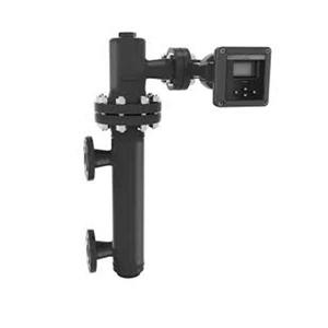
The DLC3100 digital level controller front cover comes with push buttons and a
liquid crystal display for user setup and calibration, without the need of an external
tool.
The main board and terminal assemblies are potted. Its modular design allows for
easy replacement.
The sensor module is not field replaceable, as it requires factory calibration. There
is a cover protecting the sensor module that has anti-tamper paint. This cover must
not be removed at any time to ensure accuracy.
The DLC3010 digital level controller adapter ring and terminal box are integrated in
the DLC3100 digital level controller housing. The terminal box is on the side of the
housing and has two electrical conduit entries on the bottom. This bottom entry
minimizes water ingress by self-draining when installed in its orientation.
The terminal assembly has six terminals. Three terminals on the left are for
a Resistance Temperature Detector (RTD) connection, while the other three
terminals on the right are for loop power. There are also two pins available for HART
communication on the bottom right of the terminals.
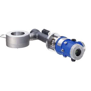
Both the DLC3010 and DLC3100 digital level controllers use the same lever
assembly. There is no change to the way that the lever assembly is coupled to the
torque tube assembly. The threaded studs on the back of the housing allows the
DLC3100 digital level controller to be mounted directly on a Fisher 249 sensor
assembly
Feature | DLC3100 HART | DLC3100 SIS | DLC3010 |
Guided Setup | Yes | Yes | Yes |
Calibration | Yes | Yes | Yes |
Setup & Calibration Log | Yes | Yes | No |
Local User Interface | Yes | Yes | No |
Process Temperature Compensation | Yes (RTD/Manual) | Yes (RTD/Manual) | Yes (RTD/Manual) |
Fluid Density Table | Yes | Yes | No |
Burst Communication | No | No | Yes |
Level Application | Yes | Yes | Yes |
Interface Application | Yes | Yes | Yes |
Density Application | Yes | No | Yes |
Alert Event Record | Yes | Yes | No |
Trip Recovery Mode | Auto | Auto/Manual | Auto |
SIL 2 Capability | No | Yes | No |
HART Version | 5 | 5 | 5 |
Table 2: Features Comparison Among HART DLC3000 Series Digital Level Controllers
DLC3010 to DLC3100 Instrument Transition Design Comparison
Electrical – Entity parameters
Entity | DLC3010 | DLC3100 | Comment |
Ui | 30VDC | 30VDC | No Change |
Ii | 226mA | 130mA | -96mA |
Pi | 1.4W | 0.9W | -0.5W |
Ci | 5.5nF | 5.5nF | No Change |
Li | 0.4mH | 0.01mH | -0.39mH |
Table 3. Electrical Entity Parameters
Performance
„ Accuracy = 0.2% of output span
„ Hysteresis = <0.1% of output span
„ Deadband = <0.05% of input span
Operating ambient temperature limits
„ DLC3100 instrument operating range: -40°C to 80°C (-40°F to 176°F)
„ LCD operating range: -20°C to 70°C (-4°F to 158°F)
„ Push Buttons: Disabled when instrument temperature is below -20°C (-4°F) or above 70°C (158°F) where LCD display might be inter